|
|

|
Detector Test System (I)
(Todavía no disponible en espańol)
EMIR is starting the
electro-optical characterisation of the HAWAII-2
FPA Rockwell IR detector plus the read-out controller.
To do this, a system is being built at the IAC headquarters, which consists
in a cryostat equipped with a filter wheel mechanism to select different
filters in the light beam to the detector and a closed cycle cooler.
The detector is placed in the fan-out board, where both, the electronical
components interacting directly with the detector and the thermal
connections, are included.
The following pictures show the steps of the fabrication and AIV process
of the system:
(Click to enlarge)
Page 1 - Page 2
| |
|---|
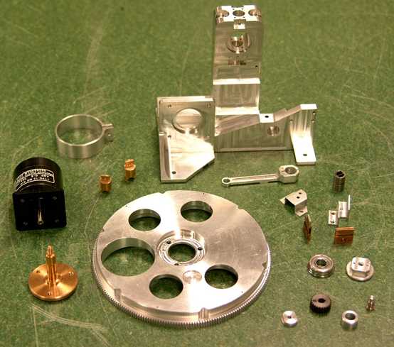
Fig. 1 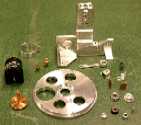 |
|
Fig. 1. Components of the filter wheel mechanism before integration.
|
| |
|---|
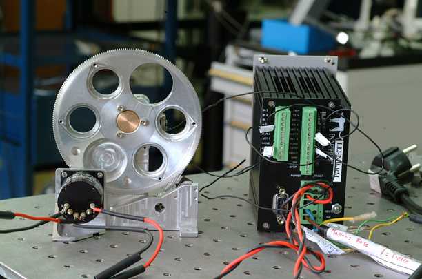
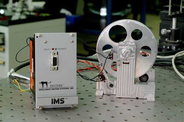
Fig. 2 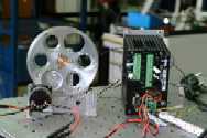 |
Fig. 3 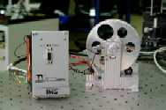 |
|
Figs. 2 and 3. Front and back views of the filter wheel mechanism
(integrated) during the room temperature operation tests. The box at the
side of the filter wheel mechanism is the motor drive controller of the
unit.
|
| |
|---|
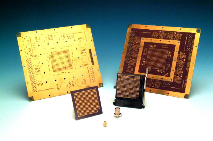
Fig. 4. 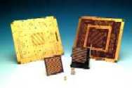 |
|
Fig. 4. Detector fan-out boards before population of components.
Detector socket, ceramic chip carrier (dummy) and some connectors in
front. Special thanks to the manufacturers: technical director Javier Ángel and
staff at Lab Circuits Company (Santa María de Palautordera,
Barcelona, SPAIN).
|
| |
|---|
Fig. 5 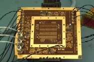 |
Fig. 6 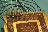 |
|
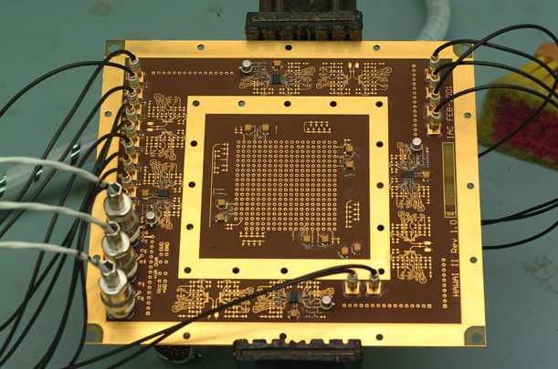
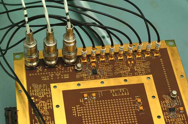
Figs. 5 and 6. Detector fan-out board after population of components and
cabling, ready for initial tests on the multiplexer. Only 4 read-out
channels will be used in this configuration.
|
| |
|---|
Fig. 7a 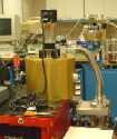 |
Fig. 7b 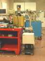 |
| |
|---|
Fig. 7c 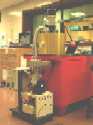 |
Fig. 7d 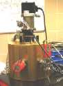 |
|
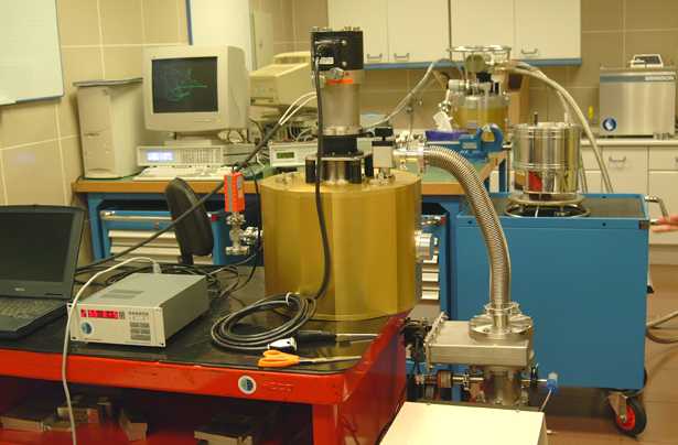
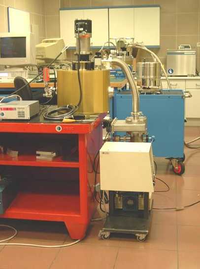
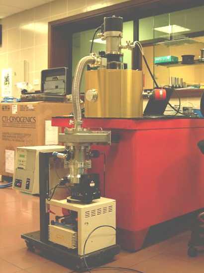
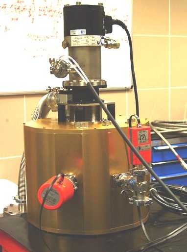
Figs. 7a, 7b, 7c and 7d. Vacuum test of the cryostat. The cryostat of the Detector
Test System (gold cylinder in the pictures), has been integrated and vacuum tested,
reaching values of the order of 10-5 mbar. The metallic hose at the
side is the vacuum pump connection (pumping mechanism is resting at
floor). The mechanism connected on top is the close cycle cooler.
|
Page 1 - Page 2
|
|